
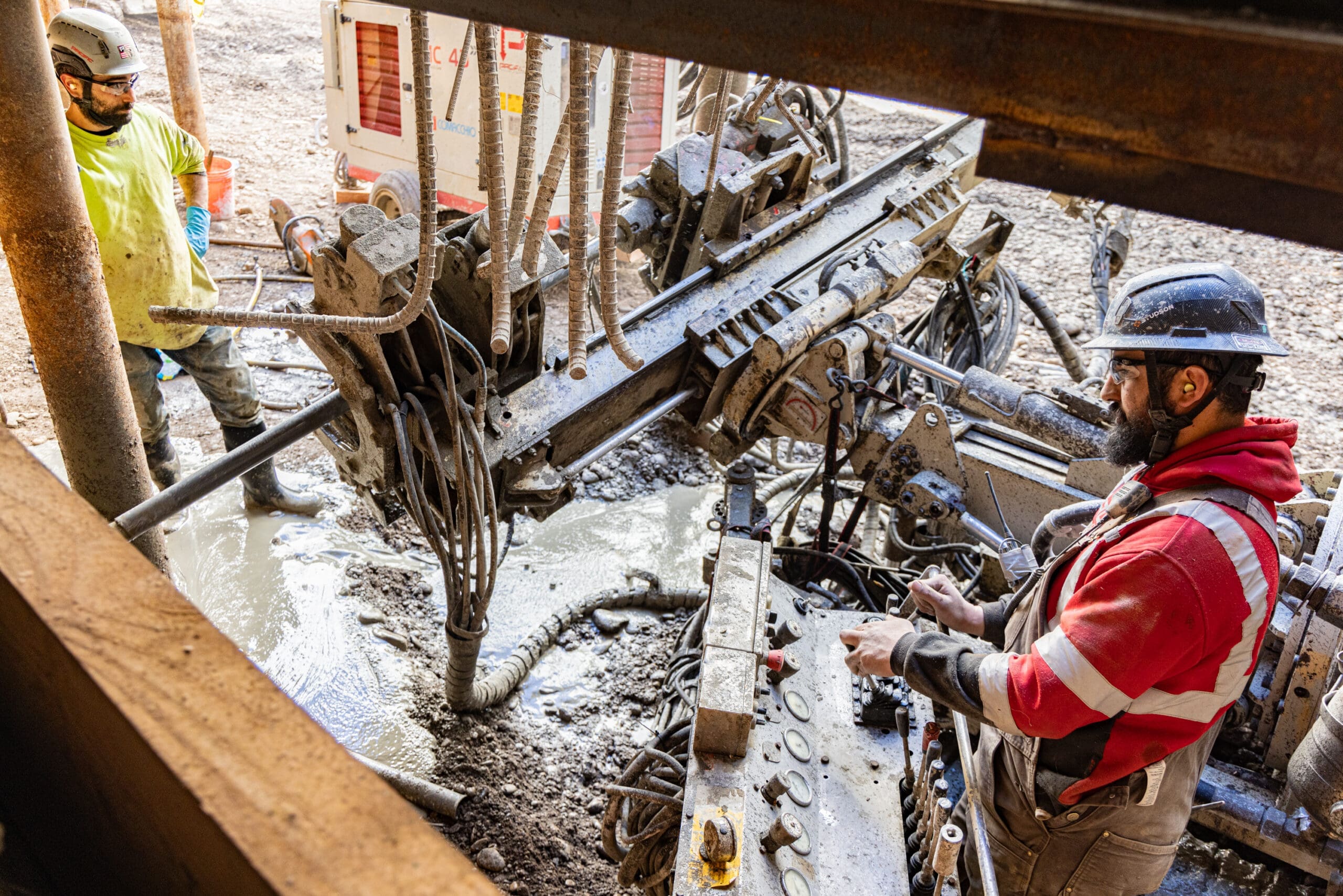
Tieback Systems
Tieback anchors provide lateral restraint to shoring and retaining walls.
Pacific Foundation’s tied-back shoring experience includes soldier piles, lagging and anchors working together through excavation. Where the ground and anchor corridor permit, tiebacks can reduce obstructions inside the cut while providing the wall support required by the design.
Where It Fits
Tiebacks are considered when a wall needs additional restraint for retained height, surcharge or movement limits. The shoring design determines the anchor arrangement and its connection to the wall.
Soldier Pile and Lagging
Anchors support soldier pile walls as excavation and lagging installation advance in stages.
Drilled Pile Walls
Tiebacks can restrain secant or tangent pile walls where the wall design and connection details provide for anchoring.
Existing Retaining Walls
Anchors may be used to restrain an existing wall when its condition, load path and connection can accommodate the proposed work.
How It Works
Tiebacks are ground anchors used to restrain shoring and retaining walls. A steel bar or strand tendon connects to the wall and transfers load through a grouted bond zone into the surrounding soil or rock. The tendon’s free length allows it to stretch during stressing, while the bond zone lies beyond the potential failure surface identified in the design.
The wall, anchorage and ground work as one system. Tiebacks can keep the excavation clearer of internal bracing, but they need suitable anchoring ground and enough space behind the wall. They do not provide a groundwater cutoff.
Anchor Components
The anchorage, free length and bond zone carry different parts of the load path.
Site Constraints
The space behind the wall matters as much as access in front of it. Confirm the anchor corridor before committing to a shoring approach.
Property and Utilities
Resolve anchor rights, easements and required owner or agency approvals before committing to the drilling corridor. Confirm buried services and nearby foundations along the proposed anchor paths.
Ground and Groundwater
Soil, rock, obstructions and groundwater affect drilling, hole support, grout placement and the bond zone.
Drilling Access
Working benches, overhead clearance and wall geometry must allow drilling, tendon handling, grouting and stressing.
Wall Movement
Nearby improvements, monitoring requirements and movement limits affect the design, excavation stages and hold points.
Construction Sequence
Tieback work follows the approved shoring design. Each anchor level must be ready for the next excavation stage.
-
Prepare the Anchor Level
Establish the wall and excavate to the specified working elevation. Confirm layout, utilities, anchor rights and access.
-
Drill the Anchor Hole
Drill to the required alignment and depth, with tooling and hole support appropriate to the ground conditions.
-
Install and Grout
Place the specified tendon and protection components. Grout the anchor and record the installation.
-
Test the Anchor
After the required grout strength develops, complete the specified load tests and provide the results for review.
-
Lock Off and Protect
Lock off at the specified load after required acceptance. Complete the anchorage and protection details.
-
Continue Excavation
Advance to the next permitted lift and repeat the sequence where further anchor levels are required.
Excavation hold points, test requirements and acceptance responsibilities are established by the project documents. The sequence must also accommodate lagging or facing, drainage and monitoring.
Testing and Protection
The specifications establish proof and performance testing, including applicable load, movement, creep and apparent free-length checks. The contract assigns witnessing, review and acceptance. Excavation proceeds after the required acceptance and lock-off. Service life and ground conditions affect corrosion protection, and the specified drilling, grouting, test and as-built records support turnover.
Project Experience
Pacific’s Washington Park Reservoir scope in Portland included temporary and permanent soldier-pile walls and tieback anchors within a broader foundation and shoring package.
View ProjectAt Julia West House in Portland, Pacific installed soldier piles, CFA shafts, lagging and tiebacks on a constrained downtown site.
View ProjectAt Press Blocks in Portland, Pacific installed soldier piles, tiebacks and lagging for the excavation-support system.
View ProjectPacific installed the secant-pile and tieback foundation-support system for Discount Tire in Clackamas, Oregon.
View ProjectPacific installed existing-wall and shoring-wall tiebacks, with soldier piles and wood lagging, at the Shiley Marcos Center in Portland.
View ProjectPacific installed permanent soldier-pile walls with tiebacks as part of the Sellwood Bridge replacement in Portland.
View ProjectRelated Services
Ground Anchors
Explore the broader anchor family.
View ServiceSoldier Pile Walls
Explore pile and lagging construction.
View ServiceSecant Pile Walls
Explore overlapping drilled walls.
View ServiceSoil Nail Walls
Compare passive reinforcement.
View ServiceCommon Questions
Are tiebacks and ground anchors the same?
Tiebacks are ground anchors used to restrain a wall or retaining structure. Ground anchors is the broader term; the application, orientation and detailing depend on the loads and supported structure.
How do tiebacks differ from soil nails?
Tiebacks are stressed to apply active restraint to the wall. Soil nails generally act as passive reinforcement as the ground deforms. The two systems have different design and construction requirements.
What if anchors cross the property line?
Anchor rights must be resolved with the affected owner or authority. If an anchor corridor is unavailable, the design team may need to consider internal bracing or another support approach.
When can excavation continue?
Follow the approved sequence after the required installation, tests, acceptance and lock-off at that support level.
Talk to an Estimator
Send the shoring drawings, geotechnical report and bid date. Include anchor loads, rights and the proposed excavation sequence.